Project 24 5V Relay

Description
Relay module is used to control high current or voltage in a circuit. It consists of a coil and a contact. When the coil is energized, the contacts close, and then the circuit is connected. When the coil is powered off, the contact and is disconnected, thus breaking the circuit.
In this project, we control the 5V relay module through the Arduino development board, so as to realize the switch control of the external circuit or equipment. When the Arduino outputs high, the relay will be triggered, and the normally open contact is closed, so then connect the external circuit; When the Arduino outputs low, the relay will return to its initial state and disconnect the external circuit.
Hardware
328 Plus development board x1
5V relay x1
LED x1
220 ohm resistor x1
DuPont wires
Working Principle
At the core of a relay is an electromagnet (a wire coil that becomes a temporary magnet when electricity is passed through it). A relay can be thought of as an electric lever; you turn it on with a relatively small current, and it turns on another device with a much larger current.
Relay Basics
Here’s a small animation showing how a relay links two circuits together.
To illustrate, think about two simple circuits: one with an electromagnet and a switch or sensor, and the other with a magnetic switch and a light bulb.
Initially, both circuits are open, with no current flowing through them.
When a small current flows through the first circuit, the electromagnet is energized, creating a magnetic field around it. The energized electromagnet attracts the second circuit’s contact, closing the switch and allowing a large current to flow.
When the current in the first circuit stops flowing, the contact returns to its original position, reopening the second circuit.
Specifications
Supply voltage – 3.3V to 5V
Quiescent current: 2mA
Current when the relay is active: ~70mA
Relay maximum contact voltage – 250VAC or 30VDC
Relay maximum current – 10A
Pinout
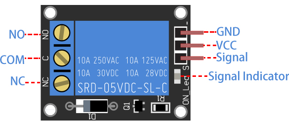
GND is the common ground pin.
VCC pin provides power to the module.
S is used to control the relay. This is an active low pin, which means that pulling it LOW activates the relay and pulling it HIGH deactivates it.
Output Terminals:
COM terminal connects to the device you intend to control.
NC terminal is normally connected to the COM terminal, unless you activate the relay, which breaks the connection.
NO terminal is normally open, unless you activate the relay that connects it to the COM terminal.
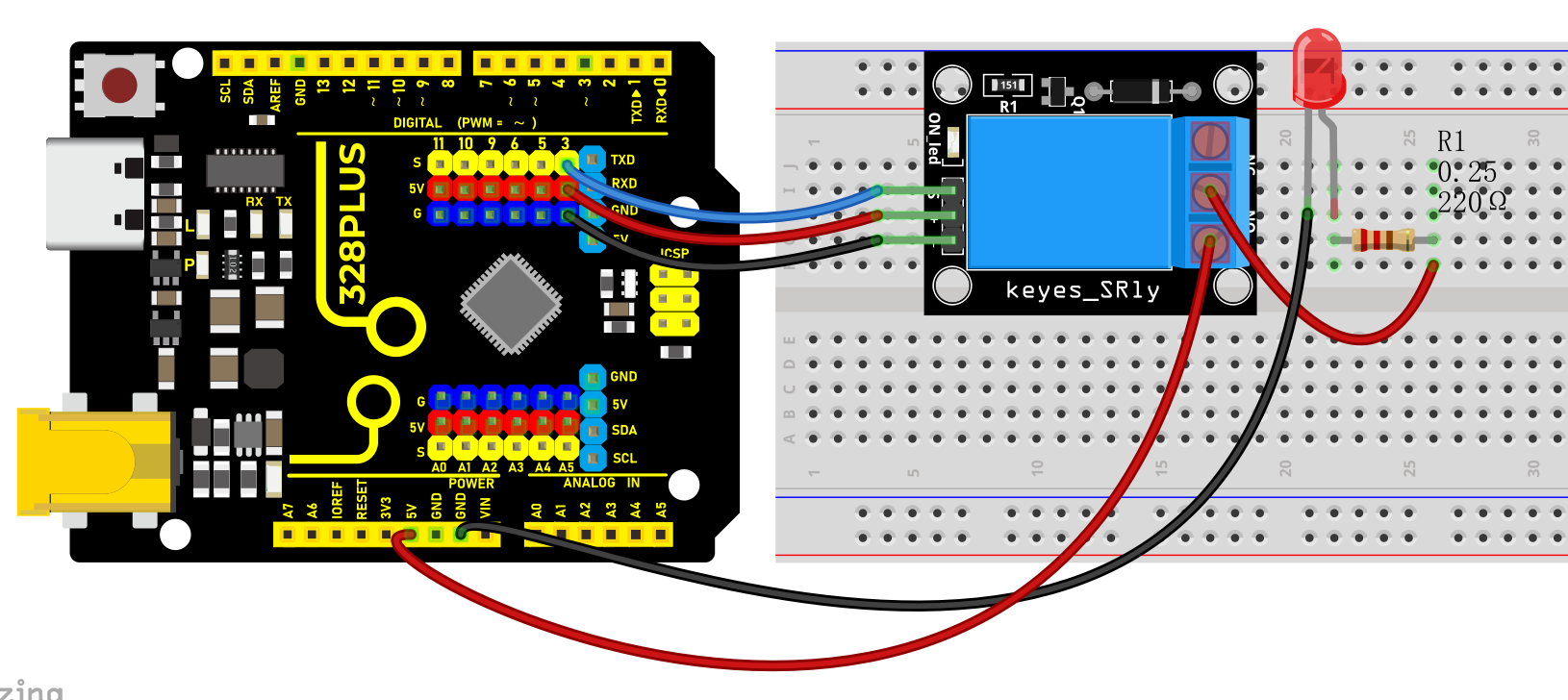
Wiring Diagram
1. Connect VCC pin of the relay to Arduino 5V
2. Connect GND pin of the relay to Arduino GND
3. Connect S pin of the relay to Arduino Digital pin D3
4. Connect an external circuit or device to the normally open and common contacts of the relay
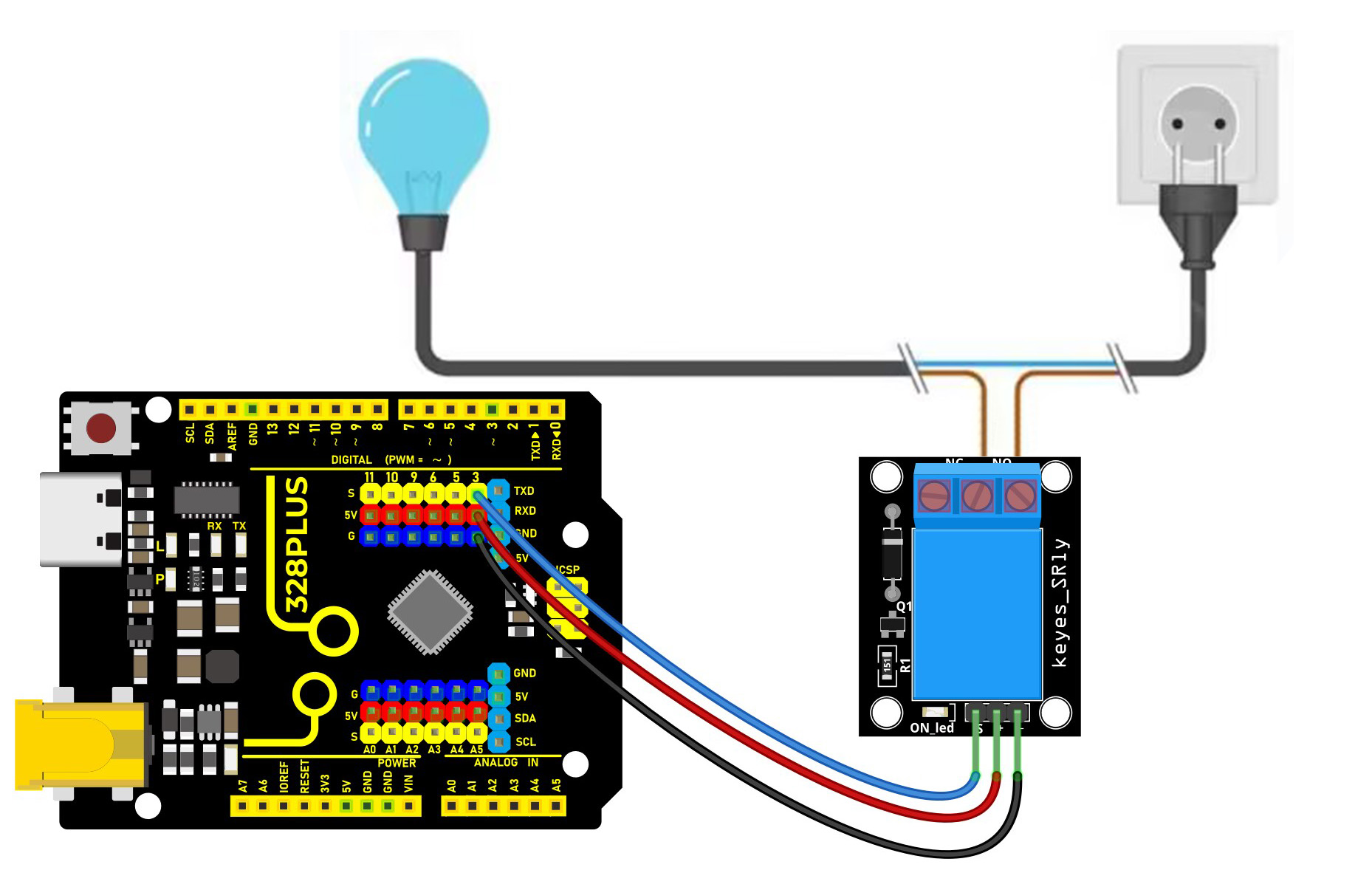
High voltage connections can be made to this screw terminal. For example: Bulb, ceiling fan etc., But in this project we are just using an LED.
When you make the connection between a) and b), the connected LED is always ON until it receives a signal from the Arduino to turn it OFF.
When you make the connection between b) and c), the connected LED is OFF until it receives a signal from the Arduino to turn it ON.
Sample Code
/*

Keye New RFID Starter Kit

Project 24

5V Relay

Edit By Keyes

*/

const int relayPin = 3; // set relay pin

void setup() {

pinMode(relayPin, OUTPUT); // set pin to output

}

void loop() {

digitalWrite(relayPin, HIGH); // output high to trigger the relay

delay(1000); // delay 1s

digitalWrite(relayPin, LOW); //output low to disable the relay

delay(1000); // delay 1s

}
Code Explanation
First, let’s start with the first line of the code:
const int relayPin = 3; // set relay pin
This line defines a constant named relayPin and assigns it a value of 3. In Arduino, const int is used to define an integer constant, which means that once assigned, relayPin cannot be changed during program execution. The number 3 here indicates that the relay is connected to digital I/O pin 3 on the Arduino board.
Next is the setup() function:
void setup() {

pinMode(relayPin, OUTPUT); // set pin to output

}
The setup() function is a mandatory part of every Arduino program. It runs only once and is used for initialization. In this function, we call pinMode(), which is a built-in function in the Arduino language used to set the mode of a specific pin. The pinMode() function takes two parameters: the pin number and the mode. Here, we set the mode of relayPin (i.e., digital pin 3) to OUTPUT, meaning this pin will be used as an output to send voltage.
Then comes the loop() function:
void loop() {

digitalWrite(relayPin, HIGH); // output high to trigger the relay

delay(1000); // delay 1s

digitalWrite(relayPin, LOW); //output low to disable the relay

delay(1000); // delay 1s

}
The loop() function is the core of the Arduino program. It repeatedly executes after the Arduino board is powered on. In this function, we use the digitalWrite() function to control the relay. The digitalWrite() function also takes two parameters: the pin number and the state (HIGH or LOW). First, we set relayPin to HIGH, which sends a 5V voltage to the relay, triggering it to close. Then, the program pauses for 1000 milliseconds (i.e., 1 second) using delay(1000);, so the relay stays closed for a while.
After that, digitalWrite(relayPin, LOW); sets the pin state to LOW, cutting off the voltage supply to the relay, causing it to return to the open state. The delay(1000); function is called again to pause the program for 1 second, and then this loop starts over.
Project Result
After uploading code, the relay changes its state (on or off) per second. When the relay is turned on, NO is connected to COM and external circuit is closed. When the relay is turned off, NO is disconnected to COM and the circuits is opened.