Project 18 Simple Smart Farm
Description
This project aims to create a simple smart farm system using Arduino. By connecting common sensors such as soil moisture sensors, photoresistors, and water level sensors, it enables real-time monitoring of soil moisture, light intensity, and water level. This system helps users understand various parameters of the plant growth environment and provides a foundation for smart agriculture research and applications.
Hardware
1.328 Plus development board x1
2.Soil moisture sensor ×1
3.Photoresistor (light sensor) ×1
4.Water level sensor ×1
5.Breadboard x1
6.jumper wires
Working Principle
Soil Moisture Sensor: Detects soil conductivity and outputs a corresponding voltage value, reflecting soil moisture level.
Photoresistor: Changes its resistance based on light intensity, generating a different voltage signal to reflect environmental lighting.
Water Level Sensor: Detects water level height and outputs a corresponding voltage value, reflecting the current water level information.
Arduino reads the analog signals from each sensor using the analogRead() function, processes them, and outputs specific values through the serial monitor for user observation and analysis.
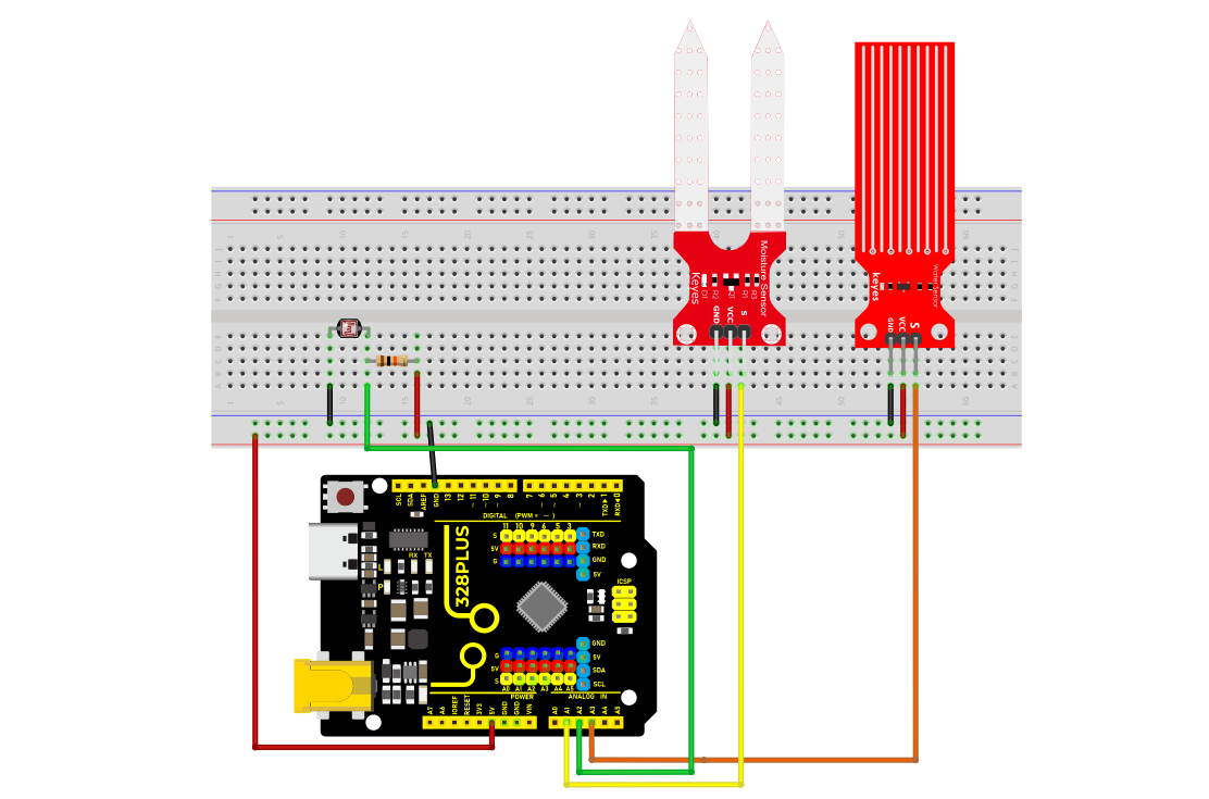
Wiring Diagram
Soil Moisture Sensor: Connects to Arduino’s A1 pin
Photoresistor: Connects to Arduino’s A2 pin
Water Level Sensor: Connects to Arduino’s A3 pin
Sample Code
/*

Keye New RFID Starter Kit

Project 18

Simple Smart Farm

Edited by Keyes

*/

// Define sensor connection pins

const int soilMoistureSensorPin = A1; // Soil moisture sensor pin

const int photoresistorPin = A2; // Photoresistor pin

const int waterLevelSensorPin = A3; // Water level sensor pin

void setup() {

// Initialize serial communication

Serial.begin(9600);

}

void loop() {

// Read sensor data

int soilMoistureValue = analogRead(soilMoistureSensorPin); // Soil moisture data

int lightValue = analogRead(photoresistorPin); // Light intensity

int waterLevelValue = analogRead(waterLevelSensorPin); // Water level information

// Print sensor data

Serial.print("Soil Moisture Value: ");

Serial.println(soilMoistureValue);

Serial.print("Light Intensity Value: ");

Serial.println(lightValue);

Serial.print("Water Level Value: ");

Serial.println(waterLevelValue);

// Wait for a while

delay(1000); // Measure once per second

}
Code Explanation
1. Pin Definitions
const int soilMoistureSensorPin = A1;

const int photoresistorPin = A2;

const int waterLevelSensorPin = A3;
-Sensor connection pins are defined using const int, making future code maintenance and modification easier.
2. Initialization Setup
void setup() {

// Initialize serial communication

Serial.begin(9600);

}
Serial.begin(9600); initializes the serial communication with a baud rate set at 9600, allowing you to view the data on the serial monitor.
3. Main Loop Function
void loop() {

// Read sensor data

int soilMoistureValue = analogRead(soilMoistureSensorPin); // Soil moisture data

int lightValue = analogRead(photoresistorPin); // Light intensity

int waterLevelValue = analogRead(waterLevelSensorPin); // Water level information

// Print sensor data

Serial.print("Soil Moisture Value: ");

Serial.println(soilMoistureValue);

Serial.print("Light Intensity Value: ");

Serial.println(lightValue);

Serial.print("Water Level Value: ");

Serial.println(waterLevelValue);

// Wait for a while

delay(1000); // Measure once per second

}
The analogRead() function reads the analog signals from each sensor, ranging from 0 to 1023.
Serial.print() and Serial.println() print the values to the serial monitor.
delay(1000); makes the program loop every 1 second.
Project Results
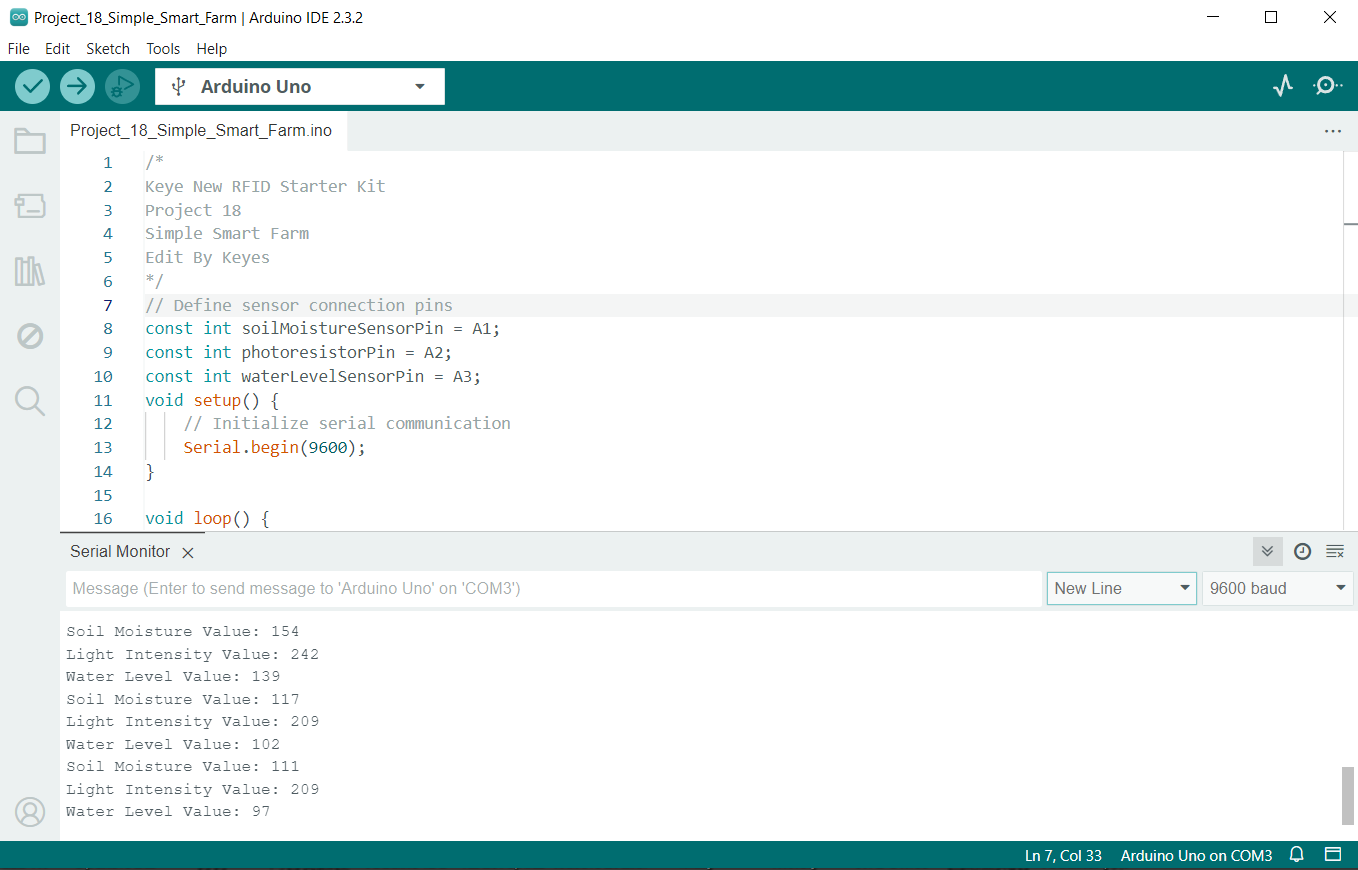
After uploading the code to the Arduino, open the Arduino IDE’s Serial Monitor , set the baud rate to 9600. You will see output similar to the following: